
Engineered to perform.
Allowable loads, connection capacities, thermal and fire data.
Every value is labeled with its source. ICC-ES ESR-5510 marks data published in the evaluation report. Values marked Manufacturer test data come from separate manufacturer testing and are not part of ESR-5510.
Structural performance
Allowable values for the evaluated panel configurations.
ICC-ES ESR-5510Allowable uniform transverse loads
ESR-5510 Table 1 · simply supported, single span, uniformly distributed load
| Span | L/180 | L/240 | L/360 |
|---|---|---|---|
| 7.5 ft | 38 psf | 38 psf | 30 psf |
| 13.5 ft | 12 psf | 12 psf | 12 psf |
| Span | L/180 | L/240 | L/360 |
|---|---|---|---|
| 9.5 ft | 14 psf | 14 psf | 14 psf |
| Span | L/180 | L/240 | L/360 |
|---|---|---|---|
| 7.5 ft | 76 psf | 70 psf | 42 psf |
| 13.5 ft | 43 psf | 43 psf | 32 psf |
| Span | L/180 | L/240 | L/360 |
|---|---|---|---|
| 12 ft | 44 psf | 44 psf | 32 psf |
- Panels require a minimum 3″ bearing width at each end; alternate support conditions must be determined by a registered design professional.
- Non-uniform loads must be converted to an equivalent uniform load for comparison. Deflection limits per IBC Table 1604.3.
- Where panels resist combined stresses, the sum of applied-to-allowable load ratios must be less than 1.0.
- For the exterior wall at 13.5 ft and the interior wall at 9.5 ft, ESR-5510 lists a single allowable load that applies across all three deflection limits.
- SIP thickness refers to the foam core thickness, as in ESR-5510.
| Configuration | Max. unsupported height | plf |
|---|---|---|
| Exterior wall (3.94″) | 9.5 ft | 922 |
- Load assumed uniformly distributed at the top of the wall, centered on the panel thickness.
| Configuration | Panel dimensions | plf |
|---|---|---|
| Exterior wall (3.94″) | 8 ft high × 8 ft wide | 144 |
- Shear wall use is limited to Seismic Design Categories A, B and C.
- Maximum aspect ratio 1:1; net deflection at allowable load was under 0.5″.
- Base connection uses M8 × 50 mm self-drilling screws at 12″ o.c. (6″ max. edge spacing) into the embedded steel channel; the connection to the supporting element is designed by a registered design professional.
Connection performance
Allowable capacities for the specific connection configurations evaluated.
ICC-ES ESR-5510| Connection | Tension | Shear |
|---|---|---|
| Cam-lock device | 210 lbf | 125 lbf in-plane · 176 lbf out-of-plane |
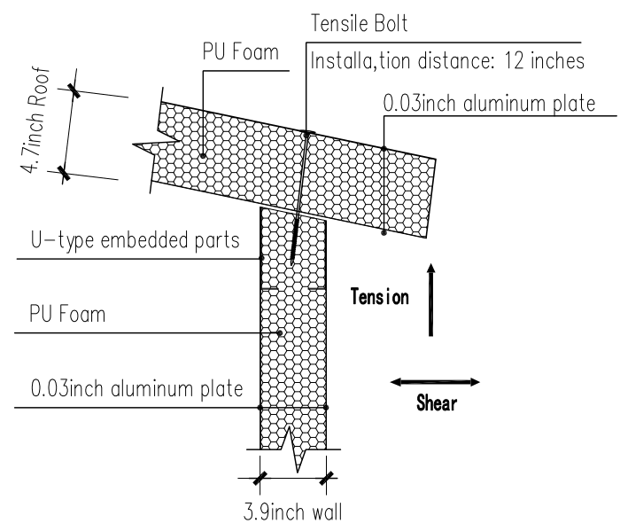
| Roof-to-wall connection | 204 lbf | 302 lbf |
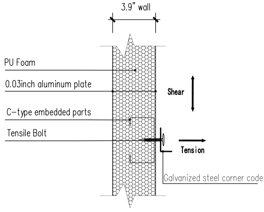
| Wall-to-steel angle connection | 377 lbf | 384 lbf |
| Header: 8 ft opening, two 4 ft × 24″ panels joined with one cam-lock | 236 plf allowable header capacity (L/360 at midspan) | |
- Screws: min. 0.31″ diameter self-drilling, 0.85″ head, ultimate shear 3,600 lbf and tension 5,400 lbf; spacing set by a registered design professional, not to exceed 12″.
- Embedded steel parts are min. 0.06″ galvanized steel, ASTM A653 SS255. Steel angles are 0.2″ thick, 2″ × 2.5″, fastened with two screws at 10″.
- Header loads must be distributed to the supporting wall panels without exceeding the cam-lock capacities above.
Each value applies to the configuration tested and described in ESR-5510. Other connections, including panel-to-foundation and connections to other supporting structure, are outside the evaluated scope and must be addressed in project design calculations and details.
Thermal performance
Core material thermal resistance, tested per ASTM C518.
ICC-ES ESR-5510This value describes the foam core material at 3″ thickness. It is not a whole-wall or whole-roof assembly R-value; assembly performance depends on panel thickness, joints, framing at openings and finishes, and is confirmed for each project.
Fire & material performance
Surface-burning characteristics of the foam plastic core and related code requirements.
ICC-ES ESR-5510- NFPA 286 room-corner test results were submitted as evidence for the evaluation.
- Steel-faced panels with a core up to 3.94″ do not require a separate thermal barrier, under IBC Section 2603.9 special approval.
- Aluminum-faced panels with a 4.73″ core must be separated from the interior by ½″ gypsum board (IBC 2603.4 / 2024 IRC R303.4).
- Roof panels with their roof covering must be shown to qualify as a Class A, B or C roof assembly as required for the building.
ESR-5510 does not assign an hourly fire-resistance rating to BOXWAY panels, and BOXWAY buildings are not fireproof. Where a project needs a rated assembly or fire separation, it must be designed and approved separately.
Additional manufacturer data
Results from separate product testing. Not evaluated in ESR-5510.
Manufacturer test data| Property | Result | Basis |
|---|---|---|
| PU core thermal conductivity | 0.026 W/(m·K) | Tested material property |
| Surface burning, panel | FSI 0 / SDI 5 | ASTM E84 |
| Wind uplift | 3.7 psi | Negative pressure capacity |
| Cyclic load | Pass / ≈ 50 plf | AC436 / ASTM E2126 |
These results come from testing outside the ICC-ES evaluation. They are useful for early design and comparison, but they are not ESR-5510 values and should not be cited as such. Contact us for the underlying test reports.
Need the numbers for a project?
Tell us who you are and what you are planning. A homeowner with one backyard, a builder with a pipeline, an engineer who needs data, or an investor looking at the platform: the form routes your inquiry to the right person.