The technology behind BOXWAY.
Panels, connections, manufacturing and logistics, designed as one system.
For builders, developers and technically minded owners. Allowable load data lives on the Performance page; the evaluation itself is explained on the ICC-ES page.
Structural insulated panels
Metal facing + PU foam core + embedded steel reinforcement.
A BOXWAY panel is a metal-faced sandwich panel with a foam-in-place polyurethane core and embedded steel tubing that stiffens the panel. The panel edges are shaped so that adjacent panels interlock with cam-lock devices. The evaluated system includes exterior wall, interior wall, roof and floor panels.
- 1 · Metal facings0.03″ 3003-H24 aluminum, or 0.02″ G60 galvanized steel, both faces
- 2 · Foam coreFoam-in-place polyurethane, nominal 2.75 pcf
- 3 · Steel tubingEmbedded Q235 steel stiffeners, hot-dip galvanized
- 4 · Cam-lockQ235 steel locking devices embedded in panel edges
- Nominal thickness
- 3″ · 3.9″ · 4.7″ (76.2 · 99.1 · 119.4 mm)
- Nominal weight
- 2.56 · 2.67 · 3.40 psf
- Width
- 48″ (1220 mm)
- Length
- Up to 16 ft (4880 mm)
- Core
- Polyurethane foam, nominal 2.75 pcf (44 kg/m³)
- Aluminum facing
- 0.03″ ASTM B209 3003-H24
- Steel facing
- 0.02″ ASTM A653 SS Grade 37, G60 galvanized
- Internal tubing
- Q235 steel, hot-dip galvanized (0.75 oz/ft²)
Panel configurations
Four evaluated panel types, each with a defined core thickness and steel layout.
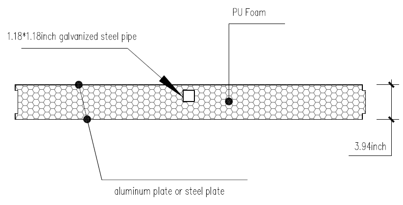
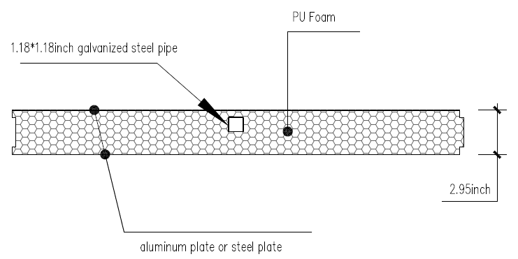
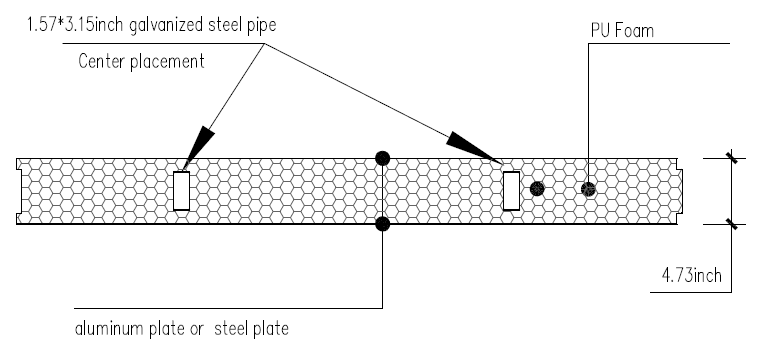
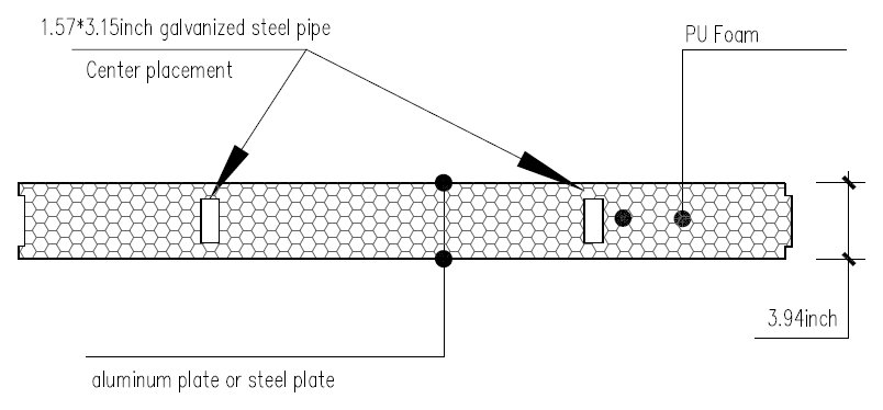
Drawings reproduced from ESR-5510, Figure 1. Facings are aluminum or galvanized steel as noted in the report.
Exterior wall panels carry axial and in-plane shear loads; roof and floor panels carry uniform transverse loads over a simple span with at least 3″ of continuous bearing at each end. Panels are used in Type V-B construction and in construction permitted under the IRC, where an engineered design is required (IRC Section R301.1.3).
Integrated connections
Cam-locks, embedded steel parts, and defined panel-to-panel details.
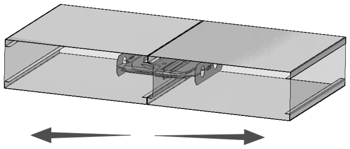
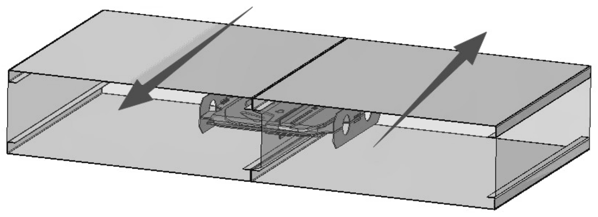
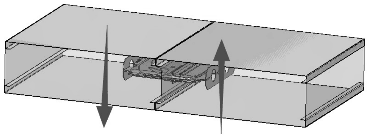
Cam-lock devices made from Q235 steel are embedded in the panel edges, including the top and bottom, and draw adjacent panels together. Embedded galvanized steel parts (U-type and C-type) receive screws at roof-to-wall, wall-to-floor and wall-to-steel connections.
Cam-lock spacing
- No more than 24″ apart at the top and bottom of a panel
- No more than 12″ from the panel edge
- No more than 40″ on center along the length
- Final spacing set by a registered design professional
Evaluated connections
- Panel-to-panel cam-lock: tension, in-plane and out-of-plane shear
- Roof-to-wall connection
- Wall-to-steel angle connection
- 8 ft opening header configuration
Capacities for each are on the Performance page. Connections to foundations and other supporting structure are outside the evaluated scope and are designed for each project. All seven typical connection details are on the Resources page.
Factory manufacturing
Controlled production, independent inspection, traceable panels.
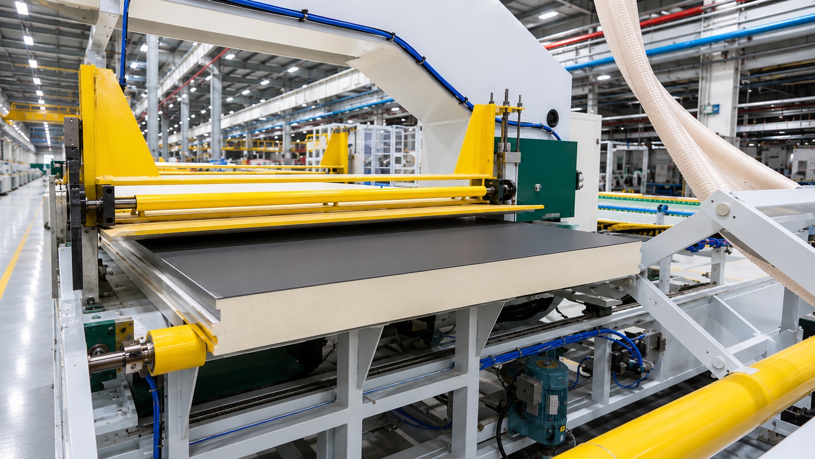
Panels are produced on a continuous line where facings, foam core, embedded steel and cam-lock hardware are brought together under controlled conditions, not assembled piece by piece on a job site.
- Manufactured under a quality-control program with inspections by ICC-ES
- Each panel labeled with the product name and dimensions
- Product labels carry the ESR-5510 number and the report holder name
- Bottom channel, wall cap and hat channel packaged separately
Flat-pack logistics
Build more in the factory. Ship it compactly. Assemble and finish on site.
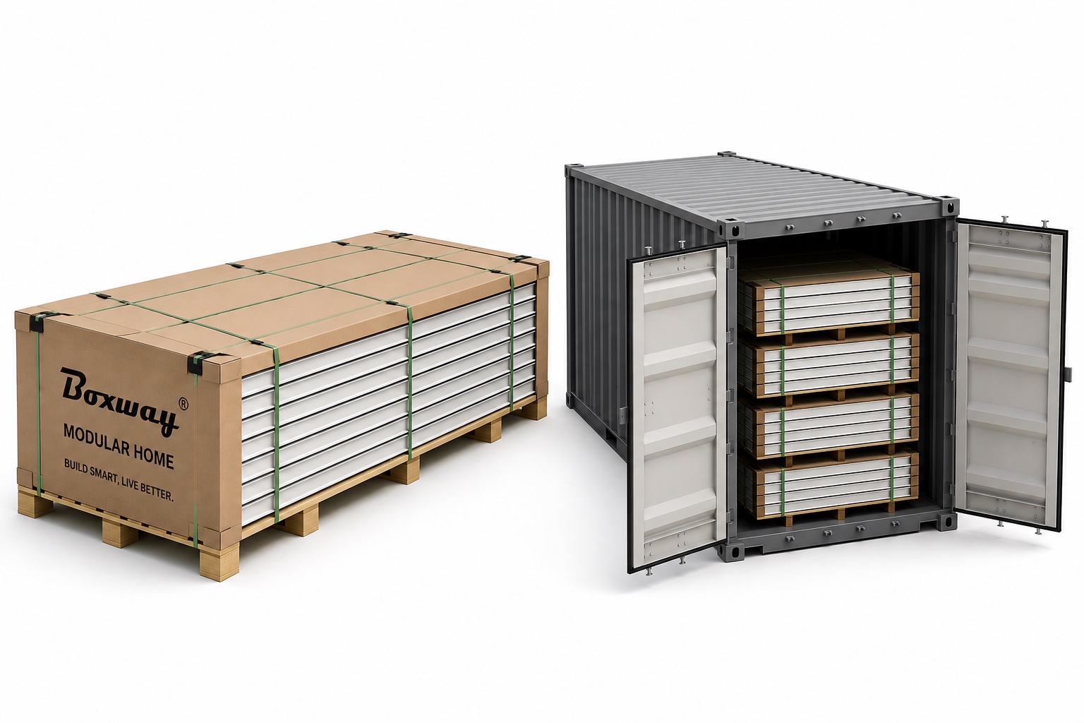
Because the structure arrives as flat panels instead of finished boxes, a complete building shell can travel stacked on pallets or in a container. That opens up sites where oversized loads, cranes or long construction schedules are a problem: rural lots, tight backyards and remote hospitality properties.
On site, a prepared local crew sets panels on a designed foundation or supporting structure, locks them together and moves on to roofing, cladding and interior finishes.
Start a Project.
Tell us who you are and what you are planning. A homeowner with one backyard, a builder with a pipeline, an engineer who needs data, or an investor looking at the platform: the form routes your inquiry to the right person.